An electrical substation is one of the most important building blocks of the power system. They are used to transform AC voltages from one level to another voltage level. We may not notice, but after generation from an electrical power plant, electrical power travels a great distance and is transformed into different voltage levels throughout its journey. Electrical substations are used to “step up” or “step down” the voltage to be delivered to where it is needed. In this article, we will discuss different types of electrical substations and equipment of a typical substation.

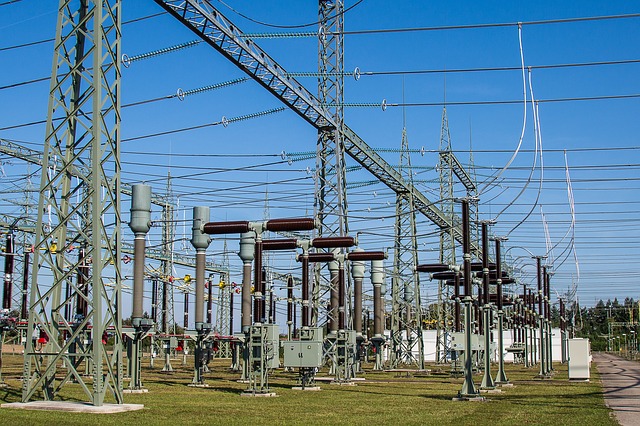
A: Primary power lines’ side B: Secondary power lines’ side
1. Primary power lines
2. Ground wire
3. Overhead lines
4. Transformer for measurement of electric voltage
5. Disconnect switch
6. Circuit breaker
7. Current transformer
8. Lightning arrester
9. Main transformer
10. Control building
11. Security fence
12. Secondary power lines
Application of Electrical Substaion:
A substation also known as an electrical grid is a key component of the electric power delivery system that makes electricity available wherever it is needed.
It accomplishes this by changing voltages from one level to another, regulating voltage to compensate for fluctuations in system voltage, switching transmission and distribution circuits into and out of the grid system, measuring electric power qualities flowing in the circuits, connecting communication signals to the circuits, eliminating lightning and other electrical surges from the system, connecting electric generation plants to the system, making interconnections between the electric systems of more than one utility, controlling reactive kilovolt-amperes supplied to and the flow of reactive kilovolt-amperes in the circuits, and so forth.
Types of Electrical Substation:
The electrical substation can be of various types depending upon its location and application. Let’s discuss them in detail.
Generating Substations:
This type of substation is used to step up the voltage from the electrical power plant’s generation voltage. Typically generation voltages can range from 11 kV (in Europe )to 13.8 kV (in the US). It is relatively economical to generate power at a lower voltage level and then step up the voltage to transmission level (138 kV, 230 kV, 500 kV in the US). Generating substations are used to evacuate the power from the power plant to the transmission line.
Typically generating substation uses three single-phase transformers instead of a three-phase transformer.
Transmission Substations:
These substations are located near the load center, and they connect two transmission lines with the same voltage level. A transmission substation may also contain a step-down transformer for convert the voltage to sub-transmission level, power quality enhancement equipment such as PFI capacitor plant, static var compensators.
Transmission substation voltage can be range from 69 to 765 kV [source]
The transmission substation has a responsibility to maintain a stable transmission line voltage and frequency.
Sub-transmission Substations:
This type of substation is connected between a transmission substation and a distribution system. It is used to step down the voltage from the transmission level to the distribution level. Typically, sub-transmission voltages can range from 33 kV to 145 kV.
Sometimes big industrial customers get their power line tapped from the sub-transmission substation.
Distribution Substations:
Electrical distribution substations are located near the customer’s load center, and they connect two or more distribution lines with different voltage levels. A distribution substation contains step-down transformers for converting the voltage from the distribution level to the customer’s premises.
Distribution substations can be from 11 kV to 33 kV and step-down to 400 V.
From distribution substations, electrical power is distributed to small industries, large commercial buildings, and residential customers through pole-mounted or underground substations.
Converter Substations:
Converter substations are a special type of electrical infrastructure, mainly power electronics-based installations such as HVDC. High Voltage DC (HVDC) is a power transmission technology that is often used as an intermediate step when converting between two AC systems.
Converter substations are also known as rectifier substations or voltage regulator stations. They are located at the point where the AC system connected to the grid meets the incoming DC system. In most cases, this point is near the load center of the distribution network.
Switching Station:
Switching stations are the last link in the power system before it reaches the customer. A switching station is basically an electrical substation without any transformer and contains only circuit breakers. As there is no transformer so they have only one voltage level.
The main function of Switching substations is switching the power source. In some areas where there is parallel power source switching stations carry out the task of switching between alternative source power in case of failure or planned maintenance.
Mobile substation:
Mobile substations are large trucks or semi-trucks mounted substations with a small distribution transformer and a couple of circuit breakers. These substations are designed to be transported to the site of the fault, where they will be set up and used to restore service. The mobile substation has to be constructed to withstand the harsh environment of the road and the elements.
The mobile substation can be moved around to where the power is needed instead of having to build a permanent facility. This makes them very useful for utility companies who must provide service to rapidly expanding or relocated populations. Another advantage of mobile substations is that they can be used to isolate sections of the grid so that maintenance can be done without affecting the rest of the grid.

For example, if you have an outage in one area, the utility company can use a mobile substation to isolate that section of the grid from the rest of the grid, so that the rest of the grid can continue to operate with full power.
Underground Substations:
Underground substations are special electrical facilities that are installed underground, typically in urban and suburban areas where overhead lines are not practical, for the purpose of distributing electrical power to the above-ground area. They are buried several feet below ground, and then they are connected by cables to the distribution system.
Compared to above-ground substations, underground substations have some advantages:
First, the cables that connect the underground substations to the transmission lines are much smaller. This means that less current will flow through the cables which reduce the voltage drop across the cables.
Another advantage of underground substations is that it provides better protection against acts of nature like tornadoes or earthquakes. The reason is that the underground cables are encased in concrete or steel and therefore the chance of them being damaged by nature is greatly reduced.
Pole-mounted Substations:
Pole-mounted substations are commonly installed by the utility company close to the area they serve. Pole-mounted substations can be used in new developments or in older neighborhoods where underground construction is impractical. Pole-mounted substations are commonly used for low voltage lines such as 11 kV to 400 V.

Elements of an Electrical Substation:
In a typical electrical power substation, there are various electrical devices. A substation electrical engineer must know about that device.
Electrical Transformer:
An electrical transformer is an electrical device that has two or more winding coils of insulated wire around a ferrous core. When alternating current (AC) flows through one of the windings, it produces a magnetic field which induces a similar but opposing magnetic field in the other winding(s). This interaction of the induced magnetic fields makes the transformer effectively step up (increase in voltage) or step down (decrease in voltage) the voltage of the AC current that flows through it. The amount of voltage change depends on how many turns are on each side of the transformer, and also on the number of turns the secondary coil has relative to the primary coil.
Transformers are the most important component in the electrical substation. If we consider the journey of the electrical power, we will see electrical power is generated at 13.8 kV and then stepped up to a transmission voltage, let’s say 138 kV. Then through a transmission line, the power is transmitted to a grid substation where this electrical power of 138 kV voltage level is stepped down to a suitable distribution level voltage 34.5 kV. In this whole journey this all voltage transformation is possible via an electrical transformer.
As we mentioned earlier that this setup is more economical than a single voltage level system, because when we stepped up the voltage in the generating station we essentially stepped down the line current, hence the long transmission line loss will also be greatly reduced.
This is why an electrical transformer is a principal equipment for an electrical substation.
Circuit Breaker:
In electrical circuits, a circuit breaker is an electro-mechanical device that opens and closes the electrical circuit. It is designed to interrupt the supply and/or the load as per the command given by the protection relay. The relay sends a signal to open the circuit breaker if the abnormal condition persists for a certain time and the circuit breaker opens the electrical circuit to protect other vital equipment from damage caused by excess current from an overload or short circuit.

In an electrical substation, typically high voltage circuit breakers are used and they are of various types.
In high voltage substations, AIS or GIS substations typically gas circuit breakers are used wherein the breaker interrupter chamber SF6 gas is being used for arc extinguishing purposes during contact breaking.
Let’s take an example: You have a 220 kV three-phase circuit that is connected to a transformer. After the transformer, the circuit is connected to a 138 kV single-phase circuit breaker. The circuit breaker will detect any fault on the 220 kV circuit (any excess current flowing on that circuit) and will interrupt the flow of electricity on that circuit.
Instrument Transformers:
Instrument transformers are used in electrical substations to measure and convert high voltage and high current to a standard level of voltages and currents so that they can be used in protection relay and metering applications. They also provide protection and isolation for the substation and equipment connected to it.
Current Transformer or CT and Voltage Transformer or VT are known as Instrument Transformer.
Protection Relays:
Protection Relays are designed to protect the substation from any unforeseen, abnormal, or hazardous conditions such as overcurrent, low voltage, high voltage, under-frequency, over-frequency, over-load, over-temperature, earth fault, and short circuit. They also protect the connected loads and connected equipment from any adverse effects of the above abnormal conditions.

The relays are connected in the supply and/or the load sides of the equipment and connected loads and they require a definite operating time to command the circuit breaker to trip and interrupt the supply and/or the load.
Disconnecting Switches:
A disconnecting switch is a mechanical device that opens and closes the electrical circuit. It is used when maintenance or repair work needs to be done on the equipment connected to the circuit. For example, if one of the transformers connected to the circuit needs adjustment or maintenance, the switch will be used to isolate the transformer from the circuit. Once the maintenance has been completed, the switch is operated to close the circuit and make it operable again.
Lightning Arresters:
Lightning arresters are connected in parallel with the circuit to prevent the flow of an over-voltage condition caused due to lightning strikes. Usually, a lightning arrester is the first element that is connected to the incoming electrical power lines.
The working principle of lightning arrestors is simple: When a lightning strike occurs, it creates a very high electrical current. This current travels through the conductor of the lightning arrester, discharging it and allowing the current to flow to the ground.
Substation Busbar:
A busbar is an assembly of metal bars or strips that carry large currents with low resistance. It is used to connect together two or more circuits of the same voltage level. All incoming and outgoing electrical conductors are connected to the substation bus, in a way bus is used as a junction box.

It’s standard practice to use copper or aluminum in the construction of electrical bus bars. One of the most important aspects of designing a bus structure is to make sure it can withstand the high short-circuit currents and mechanical forces during natural calamities.
DC Sources:
In every substation, a DC source is available, typically as a battery bank. They are mainly used to provide the dc power to the protection relays, circuit breaker auxiliary power such as close and trip coil, and charging motors.
Battery banks are very common in substations; many contain hundreds of batteries.
A battery charger is an electronic device that transforms the AC mains supply current into a direct current (DC) that is suitable for charging a battery. It works on the principle of “thyristor switching” and is the most widely used device for charging substation DC batteries.
Different Bus Configuration of Electrical Substation:
There are many configurations in which the bus bar of the electrical substation can be arranged. It is important to identify them in order to choose the best one during the substation design phase. The configurations include:
- Single Bus
- Single Bus with Bus Sectionalizer
- Main and Transfer Bus
- Double Bus Double Breaker
- Breaker and a Half
- Ring Bus
Conclusion:
After reading this article electrical engineers should have a clear idea about what is an electrical substation, what its components are, how they are connected together, the types of electrical equipment present in it, and different ways in which the bus structure can be configured. Now, it’s up to you to use this knowledge to design a practical electrical substation. Good Luck!
P.S.: Do you have any questions? If so, feel free to ask me in the comment section below.
Reference:
- https://en.wikipedia.org/wiki/Electrical_substation
- https://www.osha.gov/etools/electric-power/illustrated-glossary/sub-station