Power system state estimation is still a new branch of electrical power engineering, aged approximately three decades. Various research has been happening on this topic, but if I have to take a textbook to get a sound understanding, I would definitely take the book written by Dr. Ali Abur. It is concise and written in natural language. I will summarize the concept of state estimation in brief in this post. If you are looking for a bright and briefly written text on this topic, I think you are in the right place.
Chapter 01
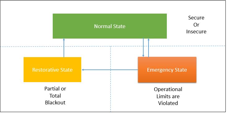
We know the set of complex phasor voltages referred to as the static state of the system. According to [1] power system has three possible states
- Normal
- Emergency
- Restorative
Normal State:
When existing generation can supply the power to connected loads without violating any “operational constraints.” The operational constraint is a term to memorize here. It simply means there are some boundaries to keep in mind, such as
- The transmission line nominal current limit
- Upper and lower limits on bus voltage magnitudes
- Though it is not mentioned in the book, operating frequency is also another constraint to keep in mind.
The normal state also has two states
- Secure
- Insecure
A normal state can be termed as secure if it is still normal after initiating a contingency from a list of predefined critical contingencies. Some relevant contingencies are transmission line or generator outages due to unexpected equipment failures or natural causes such as storms.
In simple terms, the author tried to tell the permissible event that can be tolerated after a storm or equipment failure and system to maintain normal operating conditions. In the case of natural phenomena, if one area is fed from two separate sources, it will not make the system unstable if one of the lines is disconnected.
Otherwise, the system state is considered as insecure where the system parameters appear to be balanced and inequality constrained are still satisfied. Yet, the system remains vulnerable with respect to some other contingencies.
In this circumstance, the system must take preventive measures to stop it from moving to the emergency state. Such preventive measures are determined by the security-constrained Optimal Power Flow program, which provides the list of critical contingencies.
Emergency State:
During any natural phenomena or device fault, the system state may change significantly and eventually violate the system operating constraints, yet supply power to all loads. This state might be called the emergency state, which needs immediate corrective steps. Corrective action may include load shedding. Then the system will come back to normal operating conditions with reduced loads.
Restorative State:
This brings us to a restorative state, and the actions to be taken to transform it into a normal state are referred to as restorative controls.
Power System Security Analysis and State Estimation:
Power system security analysis can be defined as the sequence of tasks done by the system operators. These tasks include monitoring and identifying the system states and determining the necessary preventive actions to maintain the system state as normal.
Data acquisition is the most vital part of doing the security analysis effectively. Then comes the analysis part. This data can be both analog and digital.
Substations are generally equipped with IEDs, which collect various types of measurement and switchgear position data and transmit them to the substation automation system. Then those data are transmitted through the telecom network to the central control center. These devices are connected with a Local Area Network, where SAS (substation automation system) works as a front-end computer. SAS shares all the data to the central control center through a Multiplexer device. The communication media can be fiber optic, radio, or satellite.
(In the book RTU is mentioned in place of IED. Though RTU is still used in the substation, IEDs are more commonly used nowadays. )
Measurement: Active power, reactive power, line current, bus voltage, incoming power, load status, transformer tap positions, circuit breaker, disconnector, and earth switch position information.